


This section presents the planning and recommendation framework for safe, resilient, and efficient e-bus depot and terminal development. It addresses key risk dimensions electrical, thermal, water, cyber, structural, and occupational safety and applies to both greenfield and brownfield depots. Emphasis is placed on preventive planning, robust engineering design, standard operating procedures, and workforce preparedness to ensure safety, asset protection, and service continuity. The recommendations respond to the rapid scale-up of e-bus adoption by public bus agency and the parallel need to both retrofit existing depots and develop new depot facilities, which are categorised as brownfield and greenfield depots, respectively.
S.No.
Responsibility
5.
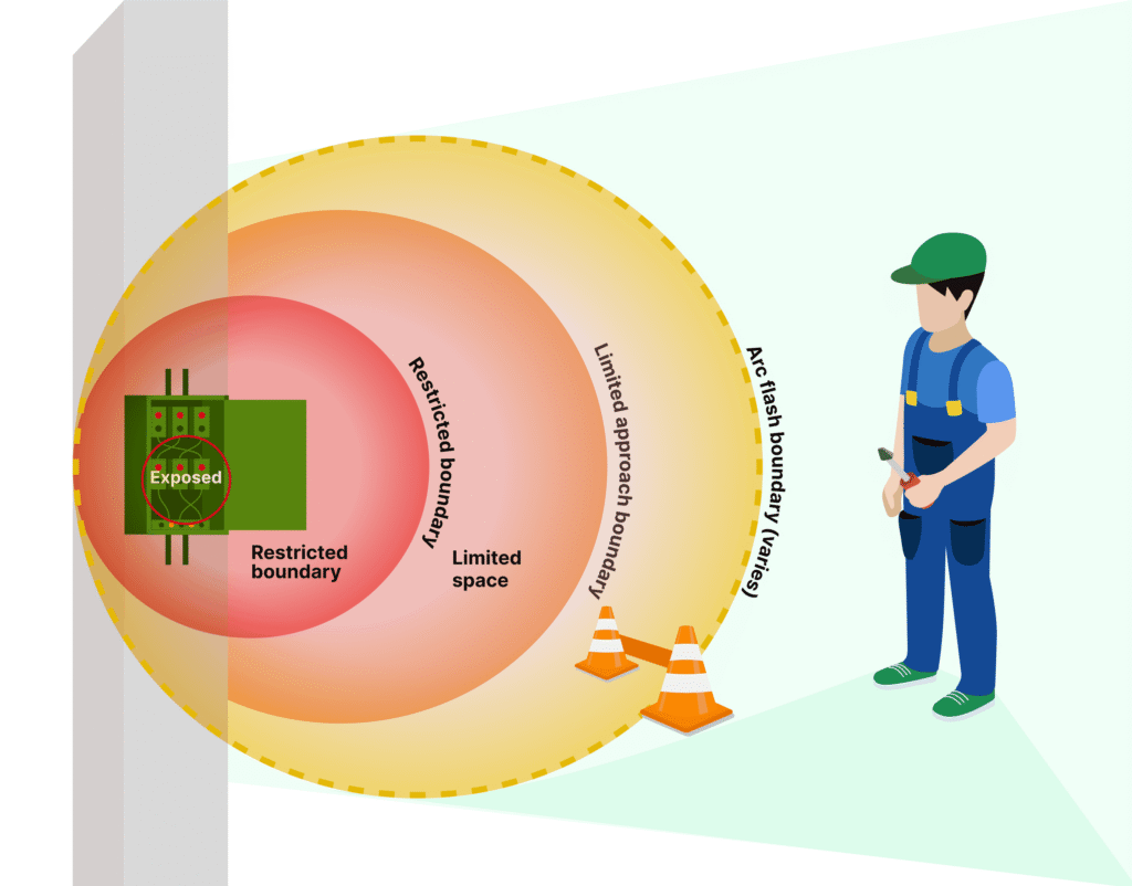
Establish safe boundaries to minimise risk of electrical injuries
Recommended Standards
The following standards shall be incorporated in the planning and design of e-bus depot and terminal by the Civil and Electrical Engineering team of the public bus transport agencies, with involvement of OEMs wherever they are part of the e-bus depot planning and design process.
Design layout is recommended to:
All depot/ terminal switchgear and control panels are recommended to:
All Electrical Infrastructure in E-Bus Depot/ Terminal must comply:
S.No.
Responsibility
Recommended Standards
The following standards shall be incorporated in the planning and design of e-bus depot and terminal by the Civil and Electrical Engineering team of the public bus transport agencies, with involvement of OEMs wherever they are part of the e-bus depot planning and design process.
Ensuring water protection requires clearly defined mitigation actions by responsible stakeholders, as outlined in the table below to facilitate enforcement and ensure compliance.
S.No.
Responsibility
Recommended Standards
The following standards shall be incorporated in the planning and design of e-bus depot and terminal by the Civil and Electrical Engineering team of the public bus transport agencies, with involvement of OEMs wherever they are part of the e-bus depot planning and design process.
S.No.
Responsibility
S.No.
Responsibility
Recommended Standards
The following standards shall be incorporated in the planning and design of e-bus depot and terminal by the Civil and Electrical Engineering team of the public bus transport agencies, with involvement of OEMs wherever they are part of the e-bus depot planning and design process.

S.No.
Responsibility
Planning Recommendations
Approval and sanctions required for both brownfield depot and greenfield depot are as follows:

Based on the planning and design recommendations outlined above, a reference e-bus depot layout has been developed to demonstrate the practical application of safety, resilience, and operational principles. The conceptual layout is designed to accommodate a fleet of 100 e-buses on approximately 5.5 acres of land, along with around 25 charging stations, and incorporates dedicated isolation zones for damaged e-buses and fire-safe areas for the storage, repair, and handling of battery packs (new, repairable, and repaired). The depot design promotes compartmentalised parking preferably in clusters of 24–25 buses with adequate separation (approximately 4–5 metres) and fire screens between compartments to limit fire spread and ensure operational continuity. A unidirectional internal circulation pattern is proposed to minimise conflict points and reduce accident risks. While non-e-bus-specific facilities follow conventional depot design standards, additional space and safety provisions are incorporated for e-bus-specific requirements, including charging zones, handling of damaged vehicles, end-of-life battery storage and disposal, and opportunity charging at terminals. Overall, the reference layout emphasises climate-resilient, structurally robust, and scalable civil infrastructure, providing a safe, efficient, and future-ready template to support the long-term sustainability and reliability of electric bus ecosystem services.
The following planning and design standards shall be incorporated in the planning and design of e-bus depot by the Civil and Electrical Engineering team of the public bus agencies, with involvement of OEMs wherever they are part of the e-bus depot planning and design process.
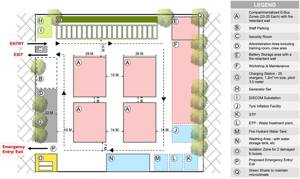
This comprehensive conceptual design layout ensures operational efficiency, safety, and resilience, enabling smooth functioning of the EBES. In particular, a well-planned internal bus‑circulation layout, with appropriately located activities and facilities, reduces manoeuvring time and enhances operational efficiency, while simultaneously ensuring compliance with fire, electrical, and overall operational safety standards.